
Halls Rotary Steam Engine 1868
“Like the searchers for the philosopher's stone, or the students of perpetual motion, the advocates of rotary engines have pursued their object with untiring diligence from one generation to another” — G.D. Hughes
Hall's Rotary Engine. - The attempts to obtain a good working engine of this class, in which the power of steam gives directly a rotary motion, have been so numerous, and the failures so complete and disheartening, that they may almost come under the category of hopeless inventions. Yet there are those who believe that we shall yet see a really good engine of this class. The following paper, read before the "British Association," by Mr. G. D. Hughes, is explanatory of another attempt to realize this hope.
PDF download here for G.D Hughes paper from Engineering Facts and Figures for 1866 and review of the Royal Agricultural Society exhibit of the Halls Rotary Engine at Leicester from Engineering July 17, 1868.
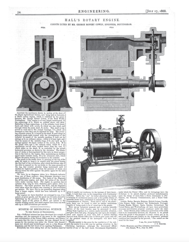
Amongst the machinery shown in motion at the show of the Royal Agricultural Society, now being held at Leicester, is Hall's rotary engine, which is cxhib1tcd by the manufacturer, Mr. George Robert Cowen, of the Beck Works, Nottingham. This engine is of very simple construction, as the engravings of it, which we publish above, will show. Refering to these engravings, A is the cylinder, truly bored, faced, and fitted with covers, D, which are also faced, and through which the main shaft, B, works. This shaft is supported at each end in the conical bearings, CC, which are arranged so that they can be adjusted for wear. The revolving eccentric piston, E, is keyed on the shaft, B, and is kept in perfectly steam-tight contact with the circumference of the cylinder by means of the metallic packing, F, held out by springs as m an ordinary piston; whilst it kept tight endways by means of the metallic rings, G G, also held up by springs against the faced surface of tho covers, DD. H is the steam inlet, and I the exhaust outlet, whilst K is an equilibrium cut-off valve worked direct from the cam, L, which slides on the shaft, B, as controlled by the patent horizontal governor, as shown in the elevation. The admission of steam is thus regulated by this valve in direct proportion to the load on the engine, thus maintaining an uniform speed under variable loads,; M is the abutment slide, which follows the piston during its revolution in the cylinder.
The steam in the steam chest, O , pressing on the top of the slide, M, tends to keep it in contact with the piston during the first half of the revolution, after which the bottom edge of the slide is exposed on the up stroke to the same pressure as the top, this counter pressure being maintained until it reaches its highest position, when the pressure of steam on the top forces the slide against the piston again for the next revolution.
We have by us diagrams taken by a Richards indicator from one of these engines; these diagrams showing a very good distribution of the steam. Two pairs of the diagrams are off the same engine, and show the action of the cut-off valve under varying loads. The engine in question has a cylinder 18 in. long;, by 14 in. diameter, and a piston 14 in. in diameter. The boiler pressure was 42lb., and the diagrams were taken when the engine was running at 150 revolutions per minute. We have also in our possession diagrams taken from a larger engine, which has been indicated up to 37 horse power.
The engines we have described are arranged to run, if required, at great speeds, and the speed can be easily altered by tightening up the governor spring on the main shaft. A surface speed of the piston of 900ft. per minute is the regular working speed, and small engines have been run with ease up to 1500 revolutions per minute.